This article is based on the following guides:
instructables.com, xilinx-wiki.atlassian.net, github.com.
FPGA development will be done in Vivado 2019.1, The necessary files for Linux will be compiled in a virtual machine Oracle VM VirtualBox, on which Ubuntu is installed.
Compilation will take place without PetaLinux, which, as Xilinx claims is a platform that contains everything you need to run Linux on FPGA and makes it easy to make changes. In this manual however, everything will be assembled manually, in order to take a closer look at the work of embedded systems.
The system boot process is described by the following scheme, taken from UG1165 and UG873:
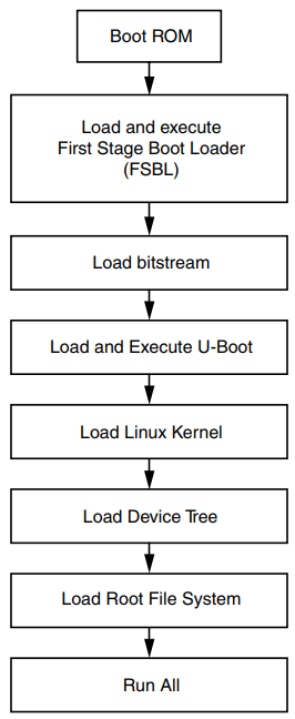 |
| Fig. 1 system load chart |
Boot ROM - execution of instructions contained in a dedicated FPGA memory, they carry out initial initialization, select the media in which the FSBL search will be performed and launch it. You cannot change this code, the rest of the files must be prepared.
So, let's begin.
The first step is to create a project in Vivado. To check the board's performance and correct settings, you can use a ready-made project from Xilinx located on github, it is implemented on version 2017.4. But this tutorial uses version 2019.1 and creates a project from scratch. Nevertheless, there you can see the correct settings for DDR and QSPI.
In the Zybo development board, the XC7Z010CLG400C-1 is used and should be selected when creating the project. Xilinx recommends using off-the-shelf libraries for its debugging boards, when creating a project, instead of a specific chip. As they say it facilitates the connection of various interfaces, a detailed description is here. But in order not to be tied to specific libraries, we will select the necessary chip separately.
 |
| Fig.2 Chip selection |
After that, you will need to connect the pins FCLK_CLK0 and M_AXI_GP0_ACLK, so the frequency is fed to the AXI interface, it will not be used at the moment, but without this you cannot compile the project.
 |
| Fig.3 processor IP core |
Connection and used components can be viewed on the scheme, which is in the public domain.
Double-click to open the IP settings of the processor core, for starters, in the section "Clock configuration", set the correct CPU clock frequency. Clock signals are sent to the output PS_CLK_500, and what it is connected to can be found on page 9:
 |
| Fig.4 CPU clock generator |
Let's put it inside Vivado:
 |
| Fig.5 Setting the processor clock frequency |
 |
| Fig.6 RAM memory |
 |
| Fig.7 RAM settings |
 |
| Fig.8 Configuring delays on PCB tracks |
 |
| Fig.9 Configuring interfaces |
 |
| Fig.10 Configuring interfaces (2) |
 |
| Рис.11 Настройка интерфейсов (3) |
 |
| Fig.11 Configuring interfaces (3) |
After that you need to compile the project. Then export it to the SDK by clicking File -> Export -> Hardware. In the window that appears, you need to put a tick next to "Include bitstream" and click ok.
The final step is to run the SDK via File -> Launch SDK. Thereafter, changes will no longer be required in Vivado.
Inside the SDK, you need to create an FSBL. It will set the correct frequency and DDR settings along with QSPI. Also download all files to ram. Additional information: Video from Xilinx about FSBL. Xilinx wiki FSBL, TRM UG585, UG821. To do this, create a new project File -> New -> Application project.
 |
| Fig.13 Creating a new project |
 |
| Fig.14 Selection of FSBL |
Further, most of the work will occur in Linux. You will also need to transfer files between two OSs, how it's done in Oracle VM described here.
All required files can be found at xilinx-wiki.atlassian.net.
Additional information about U-Boot and compilation: Build U-Boot.
The easiest way to download files it through Git, is to install it execute:
sudo apt-get install git-core
U-Boot
git clone https://github.com/Xilinx/u-boot-xlnx.git
After that, the u-boot-xlnx folder will appear in your home directory.
It is necessary to go into it and run the command line there.
It is necessary to go into it and run the command line there.
cd u-boot-xlnx
Next, run the following commands
export CROSS_COMPILE=arm-linux-gnueabihf-
export ARCH=arm
make zynq_zybo_config
If the terminal gives the following errors:
YACC scripts/kconfig/zconf.tab.c
/bin/sh: 1: bison: not found
scripts/Makefile.lib:228: recipe for target 'scripts/kconfig/zconf.tab.c' failed
make[1]: *** [scripts/kconfig/zconf.tab.c] Error 127
Makefile:496: recipe for target 'zynq_zybo_config' failed
make: *** [zynq_zybo_config] Error 2
Then you need to install the bison package:
sudo apt-get install bison
and try again. Successfully executed command looks like this:
 |
| Fig.15 U-Boot configuration |
After configuration, you must run the command
make
This will compile U-Boot, create the U-Boot.elf file in the same directory and the mkimage utility which will be used later.
Linux
The next step is to compile the Linux kernel. Read more about this xilinx-wiki.atlassian.net. First, download it using the command:
git clone https://github.com/Xilinx/linux-xlnx.git
Go to the created directory:
cd linux-xlnx
Configure the kernel:
make ARCH=arm xilinx_zynq_defconfig
make ARCH=arm menuconfig
The settings menu will open; if you don’t need additional changes, you can simply close the window:
 |
| Figure 16. Linux configuration |
We start compilation by command
make ARCH=arm UIMAGE_LOADADDR=0x8000 uImage
If an error occurs:
gcc: error: unrecognized argument in option ‘-mabi=aapcs-linux’
need to re-run the following command:
export CROSS_COMPILE=arm-linux-gnueabihf-
After compiling in the folder
linux-xlnx/arch/arm/boot
file will appear
uImage
This is the compiled kernel.
DTB
You need to use a DTB file called "Device tree". It describes to Linux which hardware is used, more on this here.
It is already compiled in the folder
/u-boot-xlnx/arch/arm/dts/
with the name
zynq-zybo.dtb
But for the sake of practice we will compile a new file, this is done by the following commands:
cd u-boot-xlnx
./scripts/dtc/dtc -I dts -O dtb -o ./devicetree.dtb ./arch/arm/dts/zynq-zybo.dts
If an error occurs:
Error: ./arch/arm/dts/zynq-zybo.dts:7.1-9 syntax error
FATAL ERROR: Unable to parse input tree
It is necessary to change the line in the dts file
#include "zynq-7000.dtsi"
on
/include/ "zynq-7000.dtsi"
The terminal should not display anything if successfully executed:
 |
| Fig.17 Compiling device tree |
If everything worked out correctly, the devicetree.dtb file should appear in the u-boot-xlnx folder.
Root File System
Now you need to create a file system with which Linux will work, when creating a U-boot, an utility was also created to create a file system.
First you need to download the file arm_ramdisk.image.gz, this page also contains a more detailed description of this step.
But still, if the downloaded file is located in the Downloads folder, then from the root directory you need to run:
First you need to download the file arm_ramdisk.image.gz, this page also contains a more detailed description of this step.
But still, if the downloaded file is located in the Downloads folder, then from the root directory you need to run:
./u-boot-xlnx/tools/mkimage -A arm -T ramdisk -C gzip -d ./Downloads/arm_ramdisk.image.gz uramdisk.image.gz
If successful, the uramdisk.image.gz file will appear in the root directory, which will be needed later.
BOOT image
Now you need to put all the files together and create a boot file for QSPI. After transferring files from Linux to Windows, return to the SDK and do the following:
Xilinx -> Create Boot Image
Xilinx -> Create Boot Image
It is necessary to add all of the created files, the .bit FPGA file is optional, if we only work with a processor. For all files except FSBL, .BIT and U-Boot, you must specify their location in memory, to do this, when adding a file, it is assigned an offset. By default, when running U-Boot with QSPI, the addresses are as follows: uImage = 0x100000, devicetree = 0x600000, uramdisk.image.gz = 0x620000. If you specify them incorrectly, an error and the correct address will be shown in the terminal at the boot stage. Default addresses can also be viewed or modified in the U-Boot source code.
U-Boot include/configs/zynq-common.h after
"qspiboot=run xilinxcmd && " \
Or inside guide for ZC702.
Also, the files should be located in the correct order, according to the time of launch, in memory they are located one after another. For FSBL in the column Partition type, instead of the datafile, you need to put a bootloader, as a result it should look like this:
 |
| Fig.18 Creating a boot image |
 |
| Fig.19 Adding offset |
To program QSPI, you need to select Xilinx -> Programm Flash. In the window that appears, add BOOT.bin to the Image File and FSBL:
 |
| Fig.20 QSPI Programming |
When programming a Zybo, you should switch to JTAG mode. After successful programming, the board should be switched to the boot mode with QSPI, through the terminal connected to the COM port (USB cable and putty terminal in my case), you can monitor the progress of the Linux boot and continue to work with it.
 |
| Fig.21 Linux ready to go |


No comments :
Post a Comment