Avr microcontrollers have several timers (counters). They can be 8 bit (max == 2^8 = 256), or 16 bit (max == 2^16 = 65536).
- Timers can count with different speeds and compute ticks
- Count from external oscillators
- With them we can compute time and time intervals (accuracy more than 0.5%)
- Generate ADC signals.
- Generate interrupts.
Prescaler / Frequency divider
Timer is able to work with the same frequency as MC, but usually we don't need that speed, so we can use prescaler, which makes out timer work at smaller frequencies, 2, 4, 8, 32, 64, 128, 256 or 1024 times less than our MC is working on.
Prescaler is a 10-bit register, which counts at the same frequency as MC, but we can choose when our timers will increase their value.
For example if we want timer to count 2 times slower, we tell it to increase it's value when bit 0 of prescaler is 0, so it will be 2 times slower -> 00, 01, 10, 11. MC ticked 4 times, but 1 in bit 0 of prescaler was only 2 times, so it is 2 times slower. 4 times slower == bit 1 etc...
Prescaler is always workig, So when you start using it, at first tick it is not necessary that you will get the time you wanted to get, because prescaler was already working and could have any value when you started using him. So it's better to restart it.
It is possible to configure different prescaler values for timers, but they still have 1 prescaler register. It means that when you restart it, that will affect all timers and prescaler starts counting from 0.
To reset the prescaler write 1 to the Special Function IO Register – SFIOR bit 0 == PSR10.
It will be set to 0 when the task is completed.
Counting register
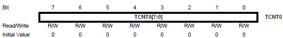
When counter receives impulse, it changes value of the counting register TCNTx by 1 (it could increase or decrease, according to the settings), x == timer number
We can write here any 7-bit number, we can choose from what value this timer will start counting, read valeus to determine how muc time passed from some event, etc.
16-bit timer consist of 2 8-bit registers TCNTxH и TCNTxL - Higher and Lower bytes. But we need to write value in 2 registers at the same time, or timer will tick and change register value while we will be writing to another register.
Atmel egnineers created TEMP register, which we can't use. To change timer value, at first we need to write to the TCNTxH, actually our value will be written to TEMP register, after that we write to the TCNTxL and right at this moment 2 bytes will be written to our timer register. It's better to disable interrupts while changing this registers.
Control Register TCCRx
Through this register we configure timer. It's the most important part. I will write about timer0, setiings differ for other timers.
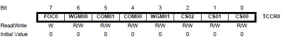
Bits CS02, CS01 and CS00 (Clock Select) determine frequency divide rate.

Bits WGM01, WGM00 (Wave Generator Mode) configure timer count mode.

TOP - is maximum timer value.
Normal - timer always count up, when it to maximum value and then restarts from 0.
CTC - Clear Timer on Compare, when timer value TCNTx matches the OCRx, timer is cleared to 0.
PWM - Pulse Witdh Modulation, i will write about it.
Register TIMSK (Timer/Counter Interrupt Mask Register)
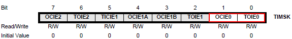
This is interrupt register, to enable interrupt we write 1 in corresponding bit. In addition interrupts must be enabled globally (7 bit of SREG register).
Бит 7 - OCIE2: Compare match Interrupt ТС2 == OCR2
Бит 6 - TOIE2: Overflow interrupt ТС2
Бит 5 - TICIE1: Input Capture Interrupt ТС1
When on pin ICP1 changes value, value of ТС1 timer is written in register ICR1 and interrupt triggered.
Бит 4 - OCIE1A: Compare match Interrupt A ТС1 == OCR1A
Бит 3 - OCIE1B: Compare match Interrupt В ТС1 == OCR1B
Бит 2 - TOIE1: Overflow interrupt ТС1
Бит 1 - OCIE0 Compare match Interrupt ТС0 == OCR0
Бит 0 - TOIE0: Overflow interrupt ТС0


No comments :
Post a Comment