
Now i will write about nokia 5110 display.
Matrix consist of 48 x 84 pixels, 48 line and 84 collumns. But power supply should be 2.7 - 3.3 V. Backlight could be powered from 5V with 1K resistor.
If you power display from 5 V, you should use 10K resistors on all pins, but either way with 5 V there could be problems with displaying and it will reduce it's life time.
On my type of display i needed to ground LED pin, to enable the backlight.
There is 2 types of pinouts:
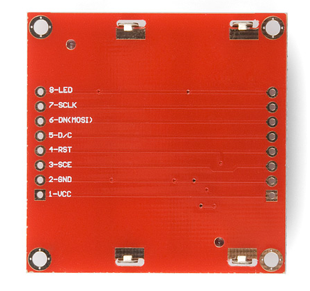

| Pin number | Designator | Function | Notes |
|---|---|---|---|
| 1 | VCC | power supply | |
| 2 | GND | ground | |
| 3 | SCE (CE) | chip select | usually grounded |
| 4 | RST | RESET | Active with log. 0 |
| 5 | D/C (DC) | choose operating mode | Commands log. 0 Data log. 1 |
| 6 | DN (DIN) | Data | 1 byte of data |
| 7 | SCLK (CLK) | Serial clock, synchronization | |
| 8 | LED (LIGHT) | Backlight | 3.3V |
Every time we communicate with display, we need to send log. 0 to the SCE pin, so i just grounded it.
After that we need to decide what are we going to send D/C = 0 for data
and D/C = 1 for commands.
Actually display read D/C pin when we pass last (0) data bit.
Data transmission works this way: We send our byte of data through DN pin, starting from last 7 bit. We set correct logical level and set SCLK pin to log. 1. After this moment data is sended, now we clear SCLK, set 6 bit on DN pin set 1 on SCLK pin and repeat the process.

Fig. 1. transmitting 1 byte
After that we can start sending second byte of data right away, if there is an error or we mistook some bit, we can cancel current data sending by clearing RST pin and now we can send new data.

Img. 2. several bytes transmission

Fig. 3. cancelling transmission
Not later than 30 ms after we turn power on, we must apply a negative pulse on the RESET pin with the length of 100 ns, otherwise you can damage the display! Thus happens initialization of the display.
Basicly all waiting between commands is <= 100 ns. So if your MC works at a frequencies of 8 MHz or less, you don't have to wait for this delay to happen.
Basicly all waiting between commands is <= 100 ns. So if your MC works at a frequencies of 8 MHz or less, you don't have to wait for this delay to happen.
Command
|
D/C
|
DB7
|
DB6
|
DB5
|
DB4
|
DB3
|
DB2
|
DB1
|
DB0
|
(H = 0 or 1)
|
|||||||||
Function set
|
0
|
0
|
0
|
1
|
0
|
0
|
PD
|
V
|
H
|
Write data
|
1
|
D7
|
D6
|
D5
|
D4
|
D3
|
D2
|
D1
|
D0
|
(H = 0)
|
|||||||||
Display control
|
0
|
0
|
0
|
0
|
0
|
1
|
D
|
0
|
E
|
Set Y address of
RAM |
0
|
0
|
1
|
0
|
0
|
0
|
Y2
|
Y1
|
Y0
|
Set X address of
RAM |
0
|
1
|
X6
|
X5
|
X4
|
X3
|
X2
|
X1
|
X0
|
(H = 1)
|
|||||||||
Temperature
control |
0
|
0
|
0
|
0
|
0
|
0
|
1
|
TC1
|
TC0
|
Bias system
|
0
|
0
|
0
|
0
|
1
|
0
|
BS2
|
BS1
|
BS0
|
Set VOP
|
0
|
1
|
VOP6
|
VOP5
|
VOP4
|
VOP3
|
VOP2
|
VOP1
|
VOP0
|
| BIT | 0 | 1 |
| PD | chip is active | chip is in Power-down mode |
| V | horizontal addressing | vertical addressing |
| H | use basic instruction set | use extended instruction set |
| D and E | 00 01 10 11 |
display blank normal mode all display segments on inverse video mode |
| TC1 and TC0 | 00 01 10 11 |
temperature coefficient VLCD 0 1 2 3 |
VOP - determines the display brightness, i set it to 0xC8
TC - temperature coefficient, responds for voltage changing in responce to the temperature changes. It coult be usefull if you LCD will be working on low temperatures, or temperature is changing frequently (home -> street)
Display divided in to a group of pixel, 8 pixels vertically, so if we want to light only 1 pixel, we still need to send information about other 7. Pixels data is stored in RAM. When we send 1 group of pixels, RAM address is incremented, so we can start sending another group of pixels.

Fig. 4. RAM format, addressing.
There is 2 types of writing pixels to the display:
Horizontal addressing is when we write block of pixels and after that we move to the right (horizontaly). When we reach last block at the right, we are moved to the left side of the next line.

Fig. 5. Horizontal addressing (V = 0).
Vertical addressing is when we move down after writing, when we reach bottom we start from the top (1 line), but in the next collumn.

Fig. 6. Vertical addressing (V = 1).
When we reach bottom right corner we start again from the beggining(X = 0, Y = 0).
Set (X) Y address of RAM - Here we choose in what block should we move our cursor. (As in Fig. 4)
Bias system - well, just write 0x13 here (according to the datasheet)
From i ebay lot i found out great library for working with the display
Font 6x8, english letters
There is great defines here, frankly i have never used them in that way. We can easily set or clear bits.
There is great defines here, frankly i have never used them in that way. We can easily set or clear bits.
#define F_CPU 8000000UL


#define LCD_RST_set  PORTD |=  (1<<0)    //external reset input
#define LCD_RST_clr  PORTD &=~ (1<<0)

#define LCD_DC_set   PORTD |=  (1<<1)    //data/commande
#define LCD_DC_clr   PORTD &=~ (1<<1)

#define SDIN_set     PORTD |=  (1<<2)    //serial data input
#define SDIN_clr     PORTD &=~ (1<<2)

#define SCLK_set     PORTD |=  (1<<3)    //serial clock input
#define SCLK_clr     PORTD &= ~(1<<3)

#include <avr/io.h>
#include <util/delay.h>
#include "english_font.h"
In cycle we send every bit, set SDIN in correspondance with our last bit of the byte, send it and shift our byte to the left, now our 6 bit is the last. We repeat the process untill we send all the bits.
void LCD_write_byte(unsigned char dat, unsigned char command)
{
 unsigned char i;

 if (command == 1)
 LCD_DC_clr;
 else
 LCD_DC_set;

 for(i=0;i<8;i++)
 {
  if(dat&0x80)
  SDIN_set;
  else
  SDIN_clr;
  SCLK_clr;
  dat = dat << 1;
  SCLK_set;
 }
}
All code#define F_CPU 8000000UL
#define LCD_RST_set PORTD |= (1<<0) //external reset input
#define LCD_RST_clr PORTD &=~ (1<<0)
#define LCD_DC_set PORTD |= (1<<1) //data/commande
#define LCD_DC_clr PORTD &=~ (1<<1)
#define SDIN_set PORTD |= (1<<2) //serial data input
#define SDIN_clr PORTD &=~ (1<<2)
#define SCLK_set PORTD |= (1<<3) //serial clock input
#define SCLK_clr PORTD &= ~(1<<3)
#include <avr/io.h>
#include <util/delay.h>
#include "english_font.h"
void LCD_write_byte(unsigned char dat, unsigned char command);
void LCD_init();
void LCD_clear();
void LCD_set_XY(unsigned char X, unsigned char Y);
void LCD_write_char(unsigned char c);
void LCD_write_english_string(unsigned char X,unsigned char Y,char *s);
int main(void)
{
DDRD = 0x0F;
LCD_init(); //LCD initialization
LCD_write_english_string(0,0," Hello World ! ");
LCD_write_english_string(0,1," bananas ");
LCD_write_english_string(0,2,"dancing potato");
LCD_write_english_string(0,3," tomato");
LCD_write_english_string(0,4," with love ");
LCD_write_english_string(0,5," from 4a4ik ");
while(1)
{
}
}
void LCD_write_byte(unsigned char dat, unsigned char command)
{
unsigned char i;
if (command == 1)
LCD_DC_clr;
else
LCD_DC_set;
for(i=0;i<8;i++)
{
if(dat&0x80)
SDIN_set;
else
SDIN_clr;
SCLK_clr;
dat = dat << 1;
SCLK_set;
}
}
void LCD_init()
{
LCD_RST_clr;
_delay_us(1);
LCD_RST_set;
_delay_us(1);
LCD_write_byte(0x21, 1); // set LCD mode
LCD_write_byte(0xc8, 1); // set bias voltage
LCD_write_byte(0x06, 1); // temperature correction
LCD_write_byte(0x13, 1); // 1:48
LCD_write_byte(0x20, 1); // use bias command, vertical
LCD_write_byte(0x0c, 1); // set LCD mode,display normally
LCD_clear(); // clear the LCD
}
void LCD_clear()
{
unsigned int i;
LCD_write_byte(0x0c, 1);
LCD_write_byte(0x80, 1);
for (i=0; i<504; i++)
{
LCD_write_byte(0, 0);
}
}
void LCD_set_XY(unsigned char X, unsigned char Y)
{
LCD_write_byte(0x40 | Y, 1); // column
LCD_write_byte(0x80 | X, 1); // row
}
void LCD_write_char(unsigned char c)
{
unsigned char line;
c -= 32;
for (line=0; line<6; line++)
LCD_write_byte(font6x8[c][line], 0);
}
void LCD_write_english_string(unsigned char X,unsigned char Y,char *s)
{
LCD_set_XY(X,Y);
while (*s)
{
LCD_write_char(*s);
s++;
}
}
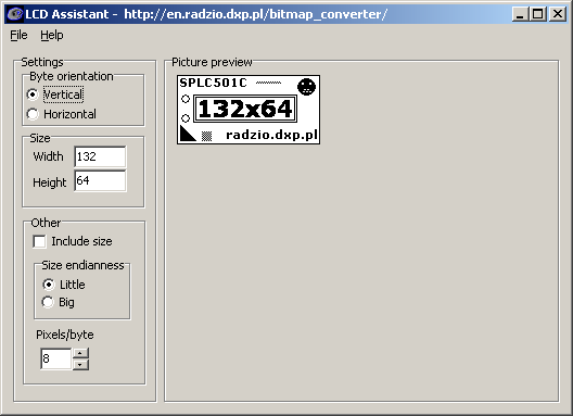
GithubThere is great proggramm for transforming images in to the code that could be displayed on our LCD
LCD Assistant
But it works only with horizontal addressing on nokia display. Because of that I decided to create my own programm and study how to work with bmp images.
Bmp to nokia 5110 Github
It creates .txt file from our image, where all information about the pixels is stored in 1 array, I will use Bender image (Futurama) (84х48).

At the end i got this file..
It can be displayed with simple cycle:
for(int n = 0; n < 504; n++)
{
    LCD_write_byte( frame_1[ n ], 0);
}
Result

After adding image, .hex file size increased by 1461 bytes.
Datasheet
Info:
Sparkfun
http://icstation.com/


No comments :
Post a Comment